Princeton Identity: Product Design Intern
Designed mechanical enclosures and calibration hardware for biometric-authentication products, integrating cameras, PCBs, sensors, and mounting features across 3 hardware programs.
- Role
- Product Design Intern
- Timeline
- Jun – Aug 2026
- Status
- Completed
- Stack
- Fusion 360
Overview
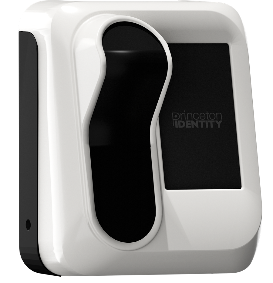
Princeton Identity builds biometric-authentication hardware, including iris- and face-recognition systems used for secure access in enterprise, government, and critical-infrastructure settings. Its products range from indoor readers to outdoor-rated scanners like the Access200w pictured above, which have to hold optical alignment and environmental sealing well outside a lab's controlled conditions. As a Product Design intern, I worked across three hardware products, designing the mechanical enclosures and fixtures that hold cameras, PCBs, sensors, and wiring together in a form that's actually manufacturable, not just something that looks right in the CAD.
The three products I worked on are still unreleased, and I'm under an NDA that covers them, so I can't show the actual enclosure CAD or photos of the hardware here. The photo above is one of Princeton Identity's existing production devices, included just to give a sense of what this category of hardware looks like. Day to day, that meant working out of a shared Fusion 360 project with the electrical and optical engineers on each product and running design reviews directly with the lead engineers whenever a change to enclosure geometry could ripple back into camera field-of-view or sensor placement, and vice versa.
My Role
I owned mechanical design for enclosure and fixture work across three product lines in Fusion 360, balancing fit, assembly sequencing, and manufacturability against the electrical and optical constraints each product's internals imposed.
On each product I started from the electrical team's PCB and sensor placement and worked outward, blocking in enclosure walls, mounting bosses, and cable routing around geometry I didn't control rather than the other way around. That constraint-first order was what caught interference issues in CAD, before they showed up as a part that didn't actually fit on the bench.
I also worked directly with contract manufacturers on draft designs, folding their DFM feedback on wall thickness, draft angles, and tolerancing back into the CAD so the parts that came back from a quick-turn vendor matched what the assembly needed the first time, instead of requiring a second design pass.
Technical Approach
Designed mechanical enclosures for 3 biometric-authentication hardware products, integrating cameras, PCBs, sensors, wiring, and mounting features while balancing fit, assembly, and manufacturability.
Each enclosure packaged the same core problem differently: camera-to-sensor alignment had to survive assembly tolerances, thermal expansion, and repeated field handling without drifting enough to degrade recognition accuracy. I modeled datum features directly off the optical assembly's own reference geometry rather than the enclosure's outer walls, so alignment was captured by the parts that actually needed to stay aligned instead of inherited indirectly through the case.
Designed an auto-focusing calibration rig, integrating motors, grippers, and supporting hardware, to automate iris-detection camera calibration in place of a manual process, improving calibration accuracy and time by 30%.
The manual process it replaced had a technician jog the camera through a focus sweep by hand and log the sharpest frame, which introduced enough operator-to-operator variation to matter downstream. The rig automates that sweep instead: a motor-driven gripper holds a calibration target at a fixed working distance, steps the camera through a defined focus range, and scores the resulting frames automatically rather than by eye. That's where both the accuracy gain and the time savings came from.
Engineered a card-reader attachment that integrated into an existing product's housing with no modification to the host geometry, designing mounts and wire routing that reduced installation to 2 screws and a single wire connection.
Because the host housing couldn't be modified, I built the mount around the reader board's actual footprint rather than a generic bracket, and routed its wiring along an existing seam in the housing's internal ribbing so the assembly still closed the way it always had. Getting installation down to 2 screws and a single wire connection took several passes on connector orientation until a field technician could complete the whole attachment without partially disassembling the host device.
Challenges
The card-reader attachment was constrained by a rule I couldn't break: no modification to the existing product's housing. That meant every mounting and routing decision had to work within geometry that was already fixed, rather than adjusting the host part to make my life easier. It was closer to retrofitting than to designing from a blank sheet.
The housing had almost no spare internal volume once its original PCB and connectors were accounted for, so the reader board and its wiring had to route through whatever clearance was left rather than a clean, dedicated channel. I ended up anchoring the new mount off two of the housing's existing screw bosses instead of adding fastener points, which kept the no-modification rule intact but meant the mount's geometry had to thread around hardware that was never designed to share space with anything else.
Running all three programs in parallel also meant context-switching between very different constraint sets week to week (a sealed, environmentally-rated enclosure one day, a motor-driven calibration rig the next) without letting assumptions from one program's design reviews bleed into another's.
Current Status & Next Steps
All three programs shipped design updates during the internship. The enclosures moved into prototyping and are on track to ship in the products once they're released, the calibration rig is nearing design completion and will replace the manual process once it's released, and the card-reader attachment got its field install down to 2 screws and a single wire connection.