5-DOF Robotic Arm with Computer Vision
A five-degree-of-freedom robotic arm that uses a wrist-mounted camera and a two-pose OpenCV triangulation pipeline to locate targets in 3D and closed-loop servo control to pick them up anywhere in its reachable workspace.
- Role
- Computer Vision Lead (paired build with Shravan Kumar)
- Timeline
- Jun – Aug 2026
- Status
- Completed
- Stack
- OpenCV, Python, MATLAB, SolidWorks/Simscape
Overview
A vision-guided pick-and-place arm built to work anywhere in its reachable volume without being told a target's height in advance. The arm detects a target with a wrist-mounted camera, triangulates its 3D position from two viewpoints, solves inverse kinematics for the pose, and closes the loop with visual feedback as it descends.
In testing it picked ground-level targets with 100% success and off-height targets (where depth estimation is harder) with 80% success.
My Role
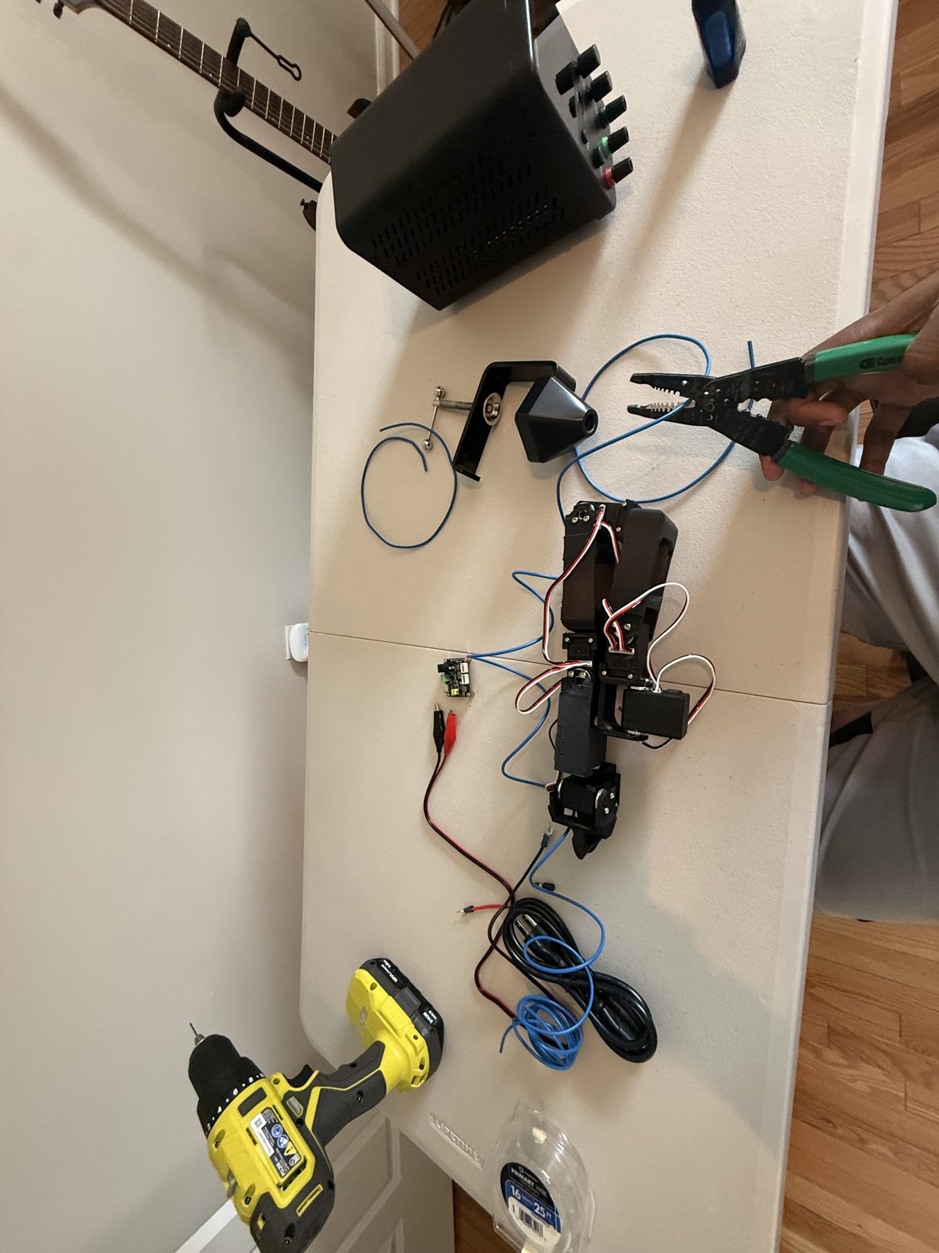
I worked across design, fabrication, assembly, and computer vision. I contributed to the mechanical design in SolidWorks, and handled fabrication and assembly: 3D printing the arm segments, wiring the servos, and bench-assembling the arm against the CAD reference.
I also built the OpenCV detection and vision-servo pipeline that drives the arm's closed-loop picks:
- segmenting the target by color and geometry
- computing its pixel centroid
- converting that into a Cartesian correction using an empirically measured millimeters-per-pixel gain
- the two-camera-pose triangulation scheme that lets a single wrist camera recover full 3D position instead of just a bearing
Shravan Kumar (Georgia Tech) led the Simscape Multibody kinematic modeling, the MATLAB inverse-kinematics solver, and hardware bring-up.
Results
Across ground-level, medium-height, and high picks, the arm hit 100% success at ground level and 80% at off-heights, where depth estimation is a harder problem. It also operates anywhere in its reachable volume without ever being told a target's height in advance.
Each pick below is shown from two angles: the phone footage is the physical arm making the pick, and the paired clip is the code and camera view driving it.
Ground-level pick
Medium-height pick
High pick
Control Loop
Each descent runs as a four-stage feedback loop. First, OpenCV segments the target and produces a pixel centroid; the resulting error vector is deliberately under-corrected rather than fully applied, since the camera rides on the wrist and any move the arm makes shifts the very measurement the correction was based on.
Second, that pixel error converts to a Cartesian offset using a live mm-per-pixel gain measured through small joint perturbations.
Third, the Cartesian target is sent over a local TCP socket to a MATLAB server, where an inverse-kinematics solver seeds from the current joint angles and converges on the nearest valid solution. Wrist roll and base yaw are locked as redundant degrees of freedom on radial moves, and every solution is checked against joint travel limits and a Cartesian floor guard.
Fourth, the resulting joint angles convert to encoder ticks and are issued over the serial bus in small, capped hops with position read-back after each one, so a stalled joint is never forced further.
Because a single camera frame only gives a ray toward the target, not a 3D point, the system captures from two poses separated by a known baseline (a base-yaw rotation) and triangulates the intersection of the two rays to recover the target's true position, including height.
That only works if the motion between poses is truly tangential (only base yaw provides the necessary perpendicular translation) and if the baseline is verified against forward kinematics rather than assumed, since a few degrees of parallax noise amplifies into a large depth error.
Pipeline
End to end, a pick moves through four stages:
- Camera → OpenCV — target detection from two camera poses
- Pose vectors → MATLAB — inverse kinematics over the surveyed chain
- MATLAB → Serial bus — paced, safety-capped servo commands
- Serial bus → Physical arm — closed-loop visual-servo descent
CAD Design
The arm is a 5-DOF chain (base yaw, shoulder pitch, elbow pitch, and wrist pitch/roll) sized around a claw with a 70.06 mm reach, modeled end-to-end in SolidWorks before any part was printed.
Wrist roll and base yaw are treated as redundant degrees of freedom on purely radial moves, which is what lets the inverse-kinematics solver lock them off and converge on a single solution instead of searching a larger null space.
I worked on this SolidWorks model alongside Shravan, and it's what every printed segment and the calibrated kinematic chain were ultimately built and measured against.
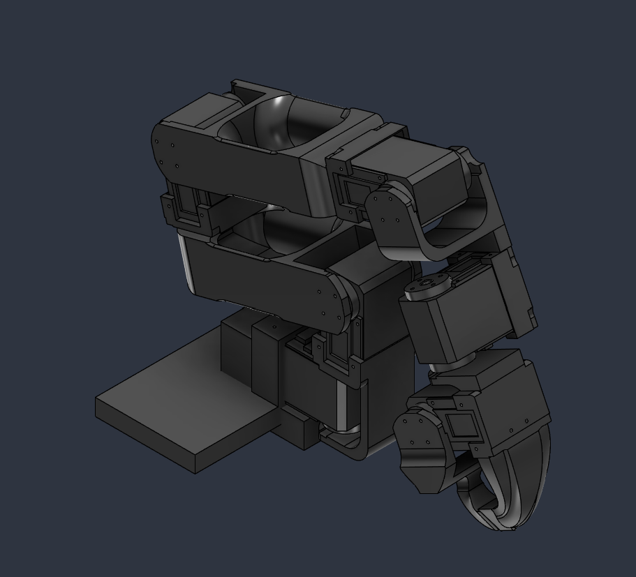
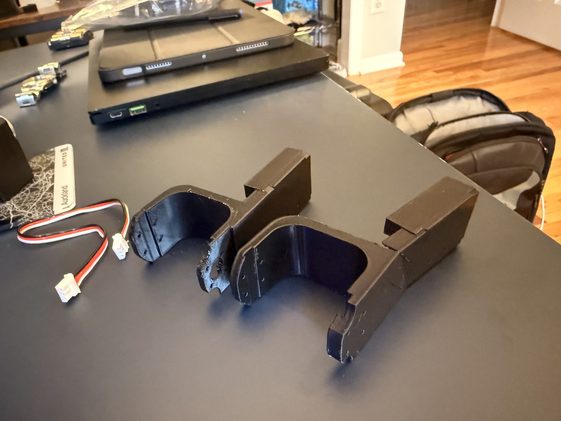
Every structural part in the design (joint brackets, servo mounts, and the links between them) was custom-modeled and printed in PLA, chosen for how cheaply a bad bracket could be reprinted while the kinematic chain was still being iterated on.
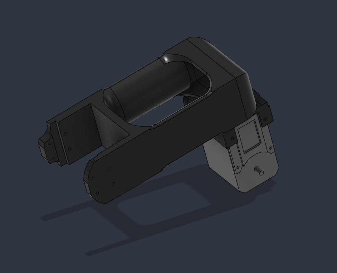
Each joint is really a small assembly in its own right: a custom PLA bracket wraps and constrains an off-the-shelf servo, so the printed part carries all the mounting geometry, bearing surfaces, and cable routing while the servo just supplies rotation.
In the close-up below, the dark grey is the custom-designed bracket; the light grey is the servo itself, dropped into a pocket sized to it.
Fabrication & Assembly
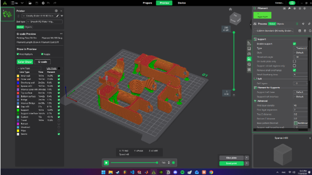
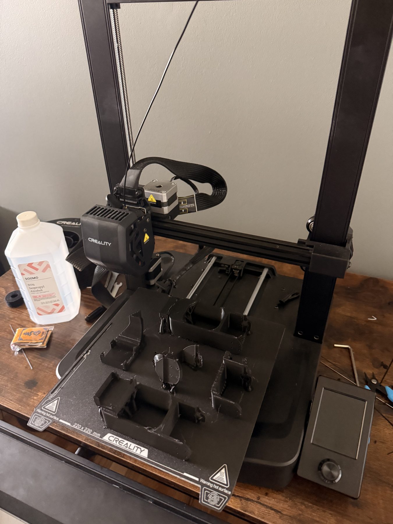
Segments were sliced and printed on a Creality Ender-class printer, then assembled and wired on the bench against the SolidWorks reference. That was the part of the build I was most hands-on with, alongside the vision pipeline.
Challenges
The imported CAD kinematic chain turned out to have its elbow moment arm inverted, a bug that four separate statistical calibration passes all missed but that a thirty-second physical ruler measurement caught immediately. That led to rebuilding the arm's kinematic chain from five directly measured physical points instead of trusting the imported CAD geometry.
A mid-move power loss also once caused a servo overload, which pushed us to harden the safety architecture: a software freeze as the first-resort stop (holding torque rather than cutting it), live torque diagnostics, per-joint travel limits measured directly on the hardware, and paced stepping that leaves room for manual intervention.
Separately, classic hand-eye calibration plateaued around 80–100 mm of error against target features of only 24 mm, which we solved by sidestepping hand-eye calibration entirely and using the two-pose triangulation survey as an independent check instead.
Accuracy
Rebuilding the kinematic chain from ten ruler measurements (no curve-fitting, no reliance on the imported CAD geometry) cut forward-kinematics error by roughly 12×:
Current Status & Next Steps
The arm is operational end-to-end and covers its full reachable workspace without any advance height input. Next up is tightening the depth-estimation confidence on elevated picks to close the gap with the ground-level success rate. Code is on GitHub.